PPT BME 311 BIOMEDICAL INSTRUMENTATION I Lecturer Ali Işın PowerPoint Presentation ID9172958
Medical applicationsecg
I am currently writing my Bachelor Project about an ECG amplifier. Common mode voltage on the body has a much higher amplitude than an ECG signal. To attenuate common mode noise a differential amplifier is used. Furthermore, a circuit known as "Driven Right Leg circuit" is used further to attenuate common mode noise.
[Resolved] Driven Right Leg circuit questions Precision Amplifiers Forum Precision

To maximize your common mode rejection ratio, you may want to consider implementing active grounding or a driven right leg in your ECG (EKG) design! Active g.
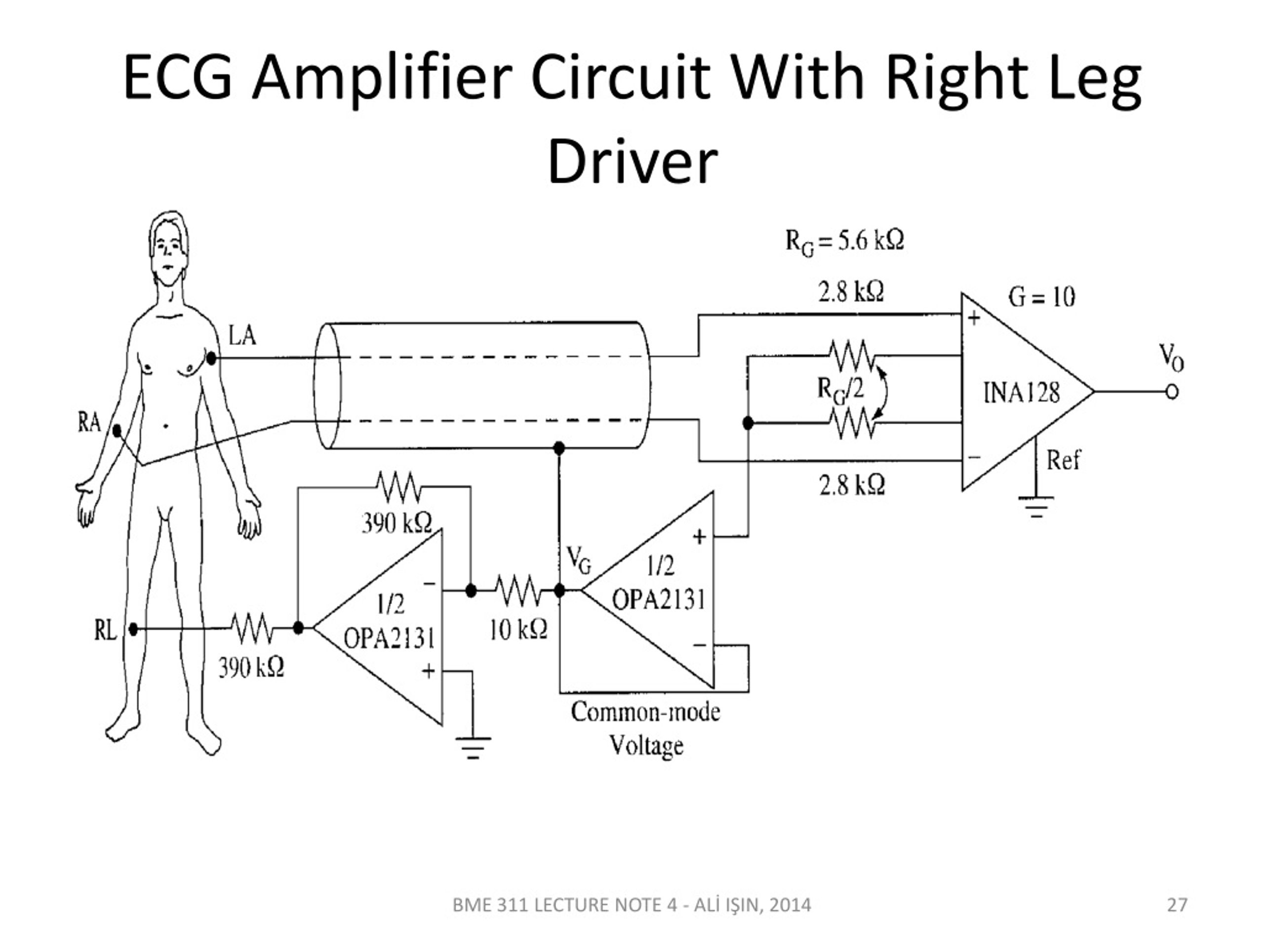
ECG amplifier with rightleg drive, as it is shown in the data sheet of... Download Scientific

The driven-right-leg circuit is often used with biopotential differential amplifiers to reduce common mode voltage. We analyze this circuit and show that high loop gains can cause instability. We present equations that can be used to design circuits that minimize common mode voltage without instability. We also show that it is important to consider the reduction of high-frequency interference.
(PDF) An ECG measurement IC using drivenrightleg circuit Alex Wong Academia.edu

6. A driven right leg (DRL) circuit is often added to a biopotential amplifier to reduce the common mode voltage (i.e. to increase the common mode rejection ratio, CMRR). A basic form of biopotential amplifier is just an instrumentation amplifier which has two stages: a buffer stage and a single output amplification stage.
PPT BME 311 BIOMEDICAL INSTRUMENTATION I Lecturer Ali Işın PowerPoint Presentation ID9172958
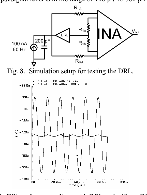
The circuit consists of an instrumentation amplifier (INA) with driven-right-leg circuit (DRL), a 5th order Gm -C low pass filter (Gm-C LPF) operating in sub-threshold mode, and amplifiers. DRL circuit is used to detect small amplitude signal in the presence of large common-mode voltage from the human body. The CMRR of the INA is 78 dB and the.
AMPLIFIER IN ECG RECORDING, DIFFERENTIAL & INSTRUMENTATION AMPLIFIER, RIGHT LEG DRIVEN AMPLIFIER

The Driven-Right-Leg (DRL) circuit has been used for about 50 years to reduce interference due to common-mode voltage in biopotential amplifiers in scenarios that range from fixed equipment.
SIGNAL CHAIN BASICS 58 Analyze the RL drive in an E... eeNews Analog

Improving CMR Using the RLD Amplifier with the ADS1298. Consider a situation when the right arm (RA) electrode is open and the left arm (LA) electrode is snug. In this case, the output common-mode of the PGA is driven away from the reference voltage, which causes the RLD feedback loop to fail.
Figure 8 from An ECG measurement IC using drivenrightleg circuit Semantic Scholar
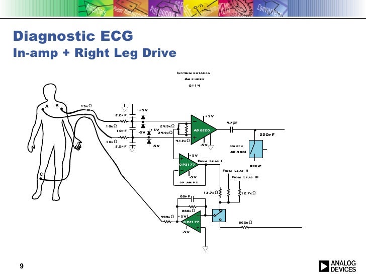
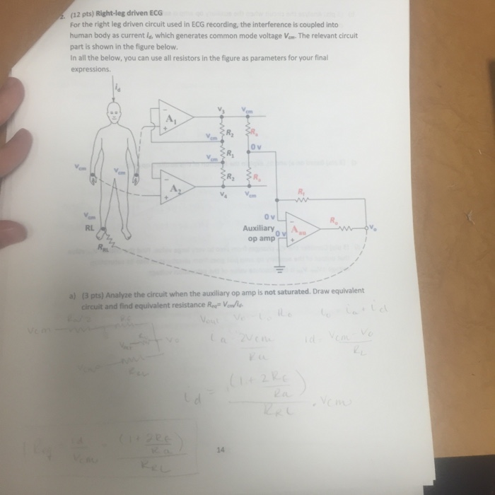
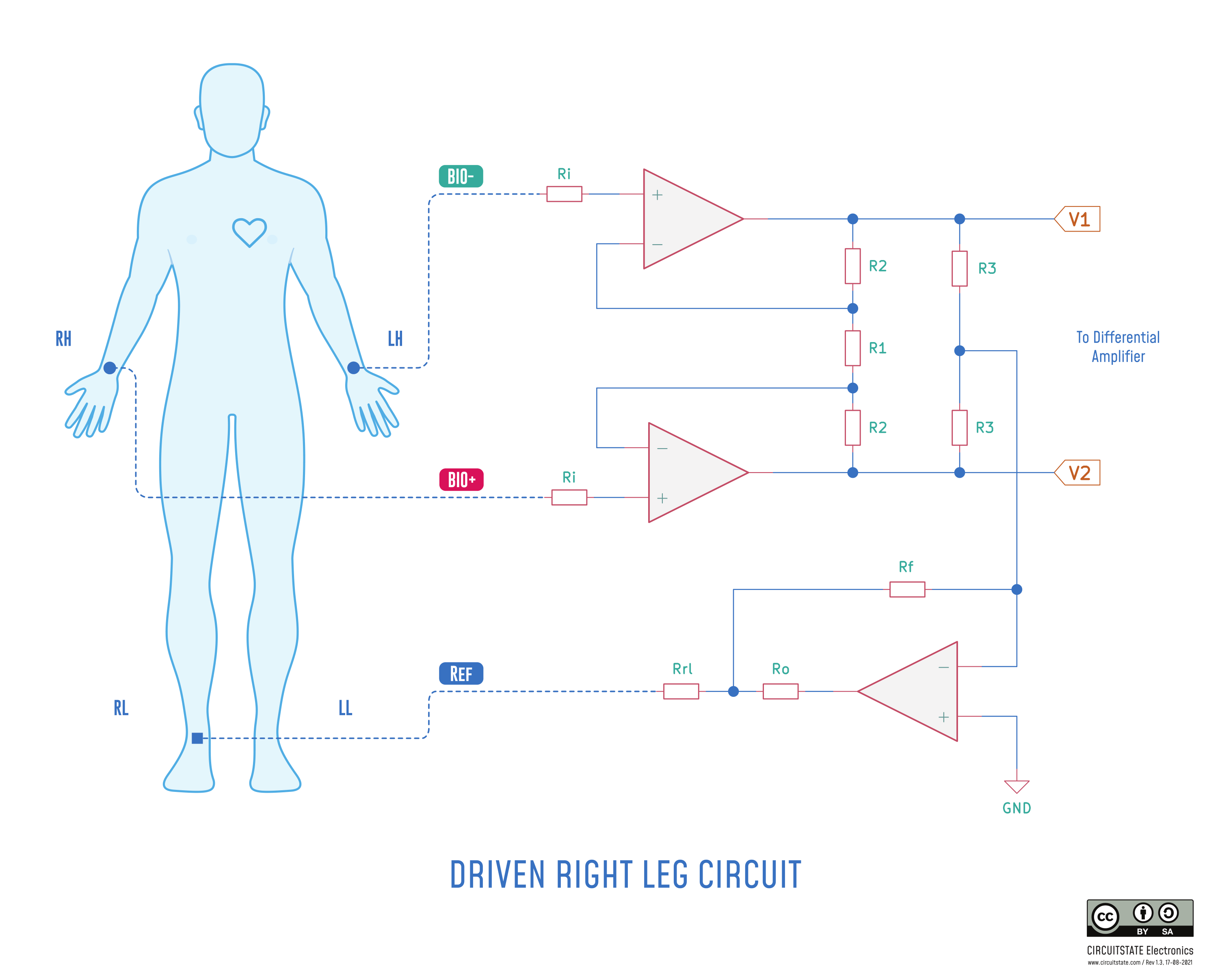
Modification to conventional ECG system Driven right−leg circuitry In modern ECG recording systems, the patient is often not grounded. Instead, the right leg electrode is connected as shown in Figure 14 to the output of an auxiliary op−amp. The common−mode voltage on the body is sensed by two averaging resistors Ra, inverted and fed
PPT ECG Signal Makeup PowerPoint Presentation, free download ID5624783

An Electrocardiogram or ECG Amplifier with Right Leg Drive is explained in this video which is the 209th example in my Analog Circuit Playlist. The first st.
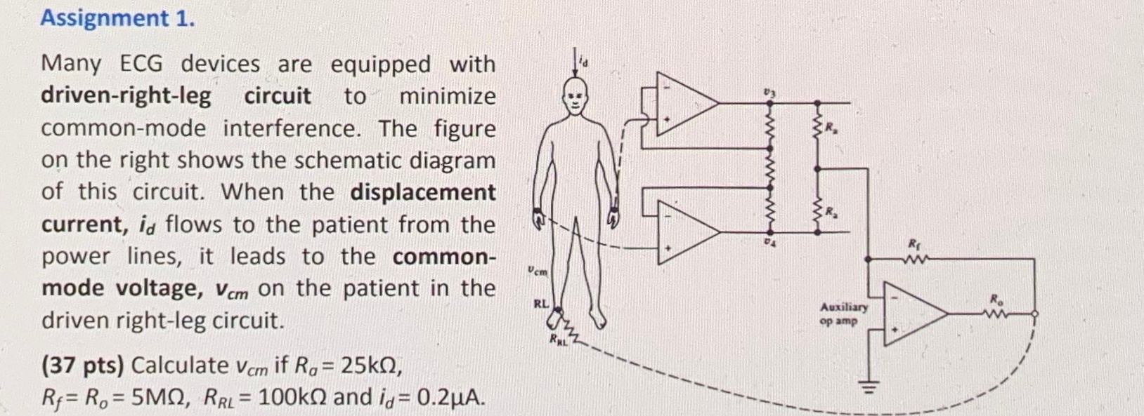
Solved Assignment 1. Many ECG devices are equipped with
A Driven Right Leg circuit or DRL circuit, also known as Right Leg Driving technique, is an electric circuit that is often added to biological signal amplifiers to reduce common-mode interference. Biological signal amplifiers such as ECG ( electrocardiogram) EEG ( electroencephalogram) or EMG circuits measure very small electrical signals.
Right Sided ECG Lead Placement EM IM Cardiology GrepMed

The feedback circuit is named DRL as it works based on the same principles as the popular driven right leg (DRL) feedback loop used in ECG recording [19]. The feedback loop improves CMRR by 20×.
ECG waveforms using different driven right leg circuits in the noisy... Download Scientific

Resistors Ra and Ra average the voltage of the differential electrode pair to sense vc. A3 amplifies and inverts this voltage and feeds it back to the body via the third electrode. For ECG systems, the third electrode is commonly applied to the right leg; hence, we have the name driven-right-leg circuit.
ECG amplifier with rightleg drive, as it is shown in the data sheet of... Download Scientific

The right-leg-drive circuit is used in the overall process to ensure good common-mode rejection ratio (CMRR) performance. For the newly designed op-amp, its gain can reach 60db, and the operating.
Solved (12 pts) Rightleg driven ECG For the right leg
A new operational amplifier (op-amp) design is proposed in this study, and it is integrated into the traditional "right-leg-drive" circuit to cancel out the common-mode interference and improve the performance of the amplifier. The low-power consumption and low-noise sensor remain an important challenge in Electrocardiogram (ECG) sensor field. A new operational amplifier (op-amp) design is.
ECG Electrode Placement GetBodySmart

The total capacitor usage is 1nF, less than the specified maximum capacitor usage. To sum up, the ECG sensor is designed using the "right leg drive circuit" and a new type of amplifier is designed to eliminate common-mode interference and improve the performance of the amplifier. Export citation and abstract BibTeX RIS.
Upside Down Labs BioAmp EXG Pill v0.7 Biopotential AFE Hardware Overview and Interfacing with
IMEC. Leuven, Belgium Aakash.Patel@imec.be. Abstract—A digital system for capacitive ECG measurement is proposed, including a digital driven right leg loop, which compared to current analog systems, can provide significantly greater robustness for the placement of electrodes in real-world scenarios such as inside a vehicle, as well as greater.